A Guide to Bounding Box Formats

Contents
What is a bounding box?
Quite simply, a bounding box is just the rectangle that contains the pixels for the object. It represents the “bounds” of the object in the image.
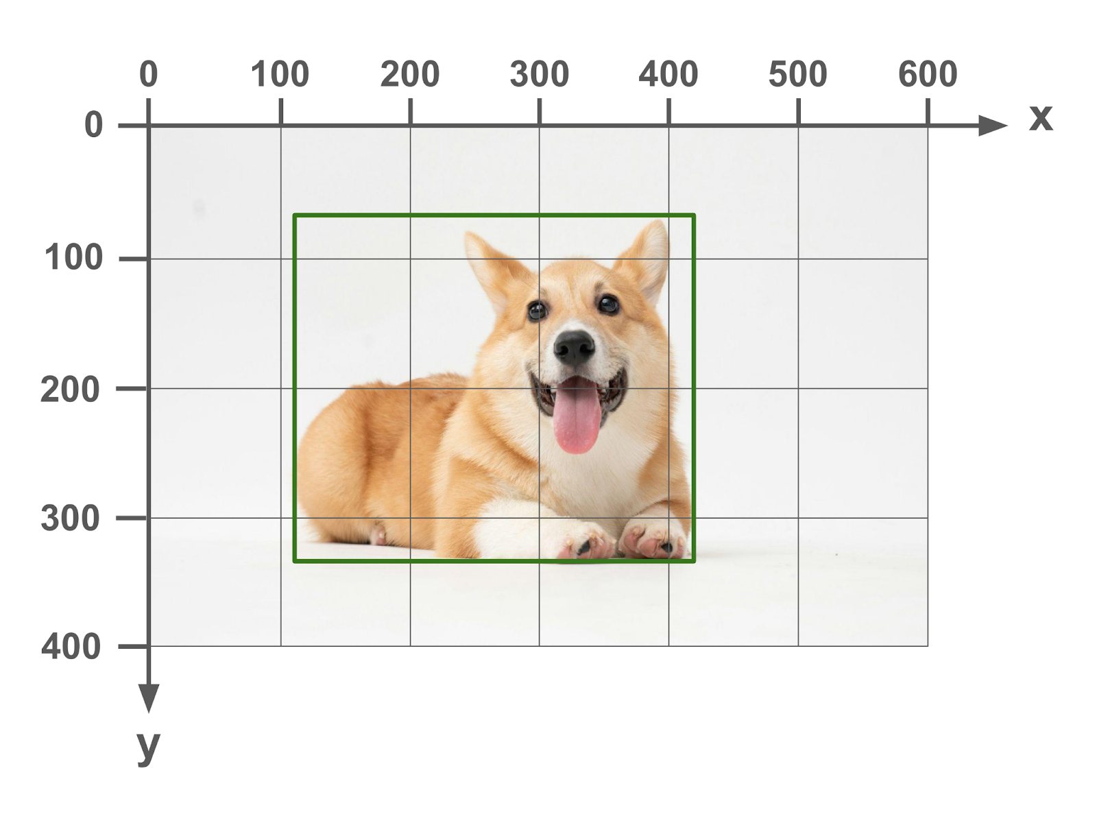
In order to describe the bounding box, the image is laid onto an x-y coordinate grid. The x-axis runs horizontally left to right, with the 0 point at the left of the image. The y-axis runs vertically up to down, with the 0 point at the top of the image.
Here is the same image with two points marked out in (x,y) coordinates.
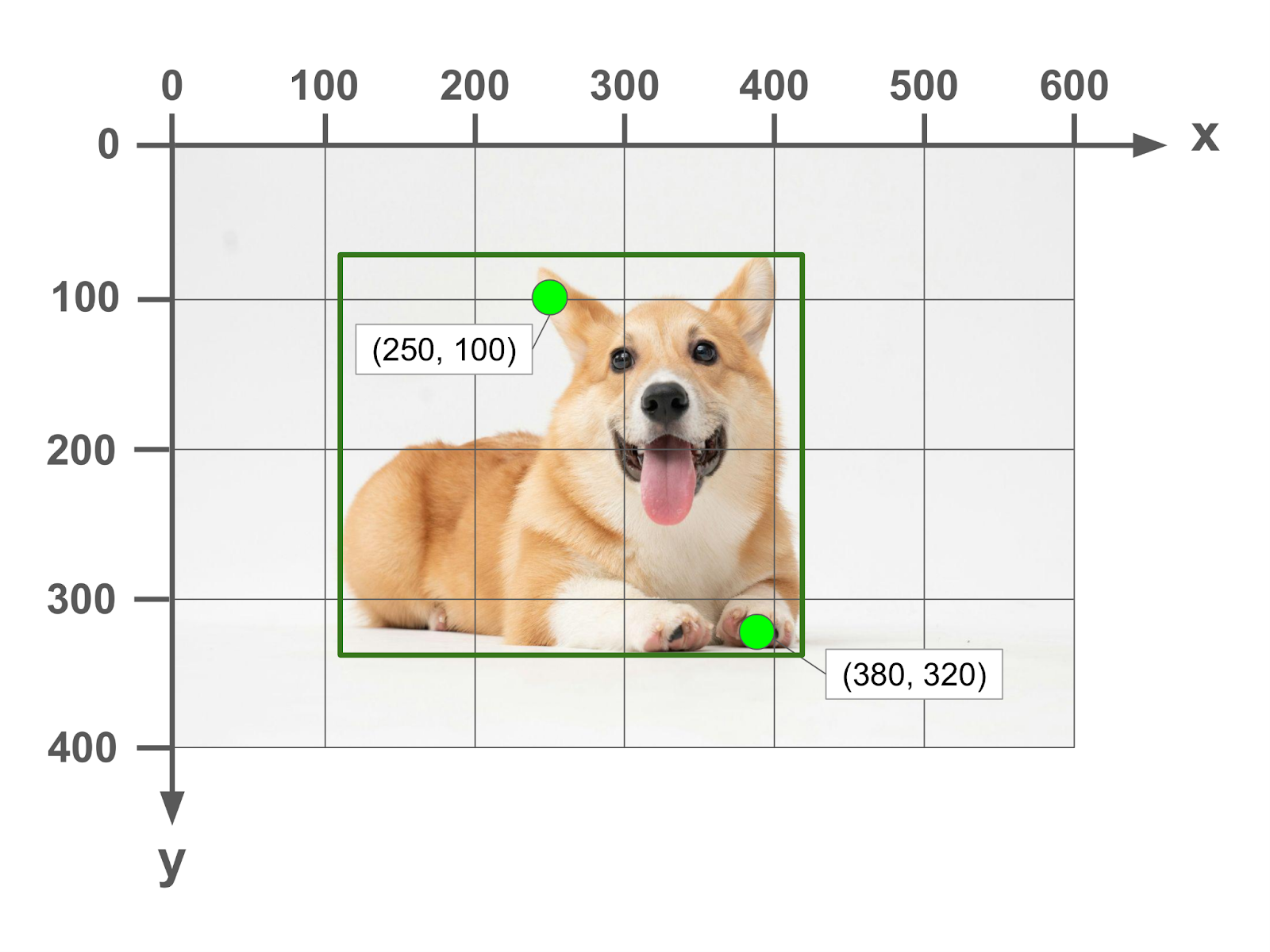
In order to specify the bounding box, we need to provide 4 pieces of information in order to be able to draw the rectangular box on the image. There are quite a few ways that this can be done, and folks have devised several formats over the years.
Key differences between formats
There are two ways that bounding box formats differ:
- Units - what units are used to express points and distances on the image
- Corner specification - how the four corners of the box are specified
Units
There are 2 units used in expressing points and distances on an image:
- Absolute (pixels) - the values are expressed in units of pixels on the image. Points are expressed in (x,y) format, which each being the distance of the origin point at the top-left of the image.
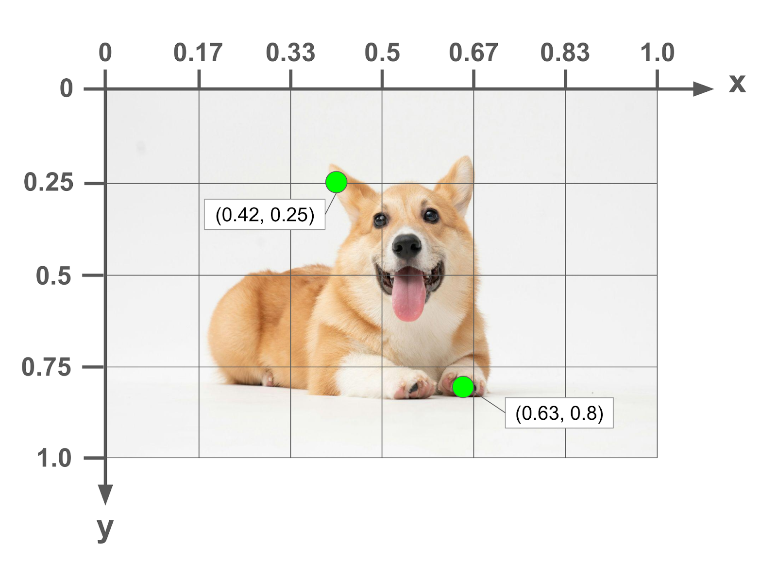
- Normalized - the values are expressed as a decimal fraction of the total height or width of the image. So a point (0.25, 0.5) would be one quarter towards the right on the x-axis and right in the middle of the y-axis.
Corner Specification
There are 3 ways that are used to express the four corners of the bounding box. All of them consist of a list of 4 numbers, but the meaning of the number in each position changes.
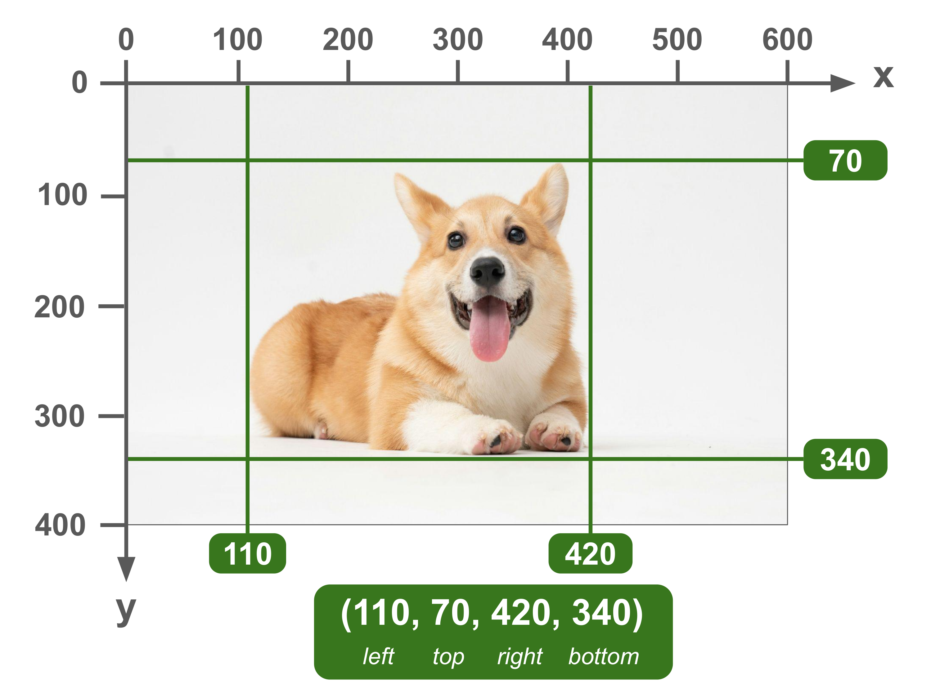
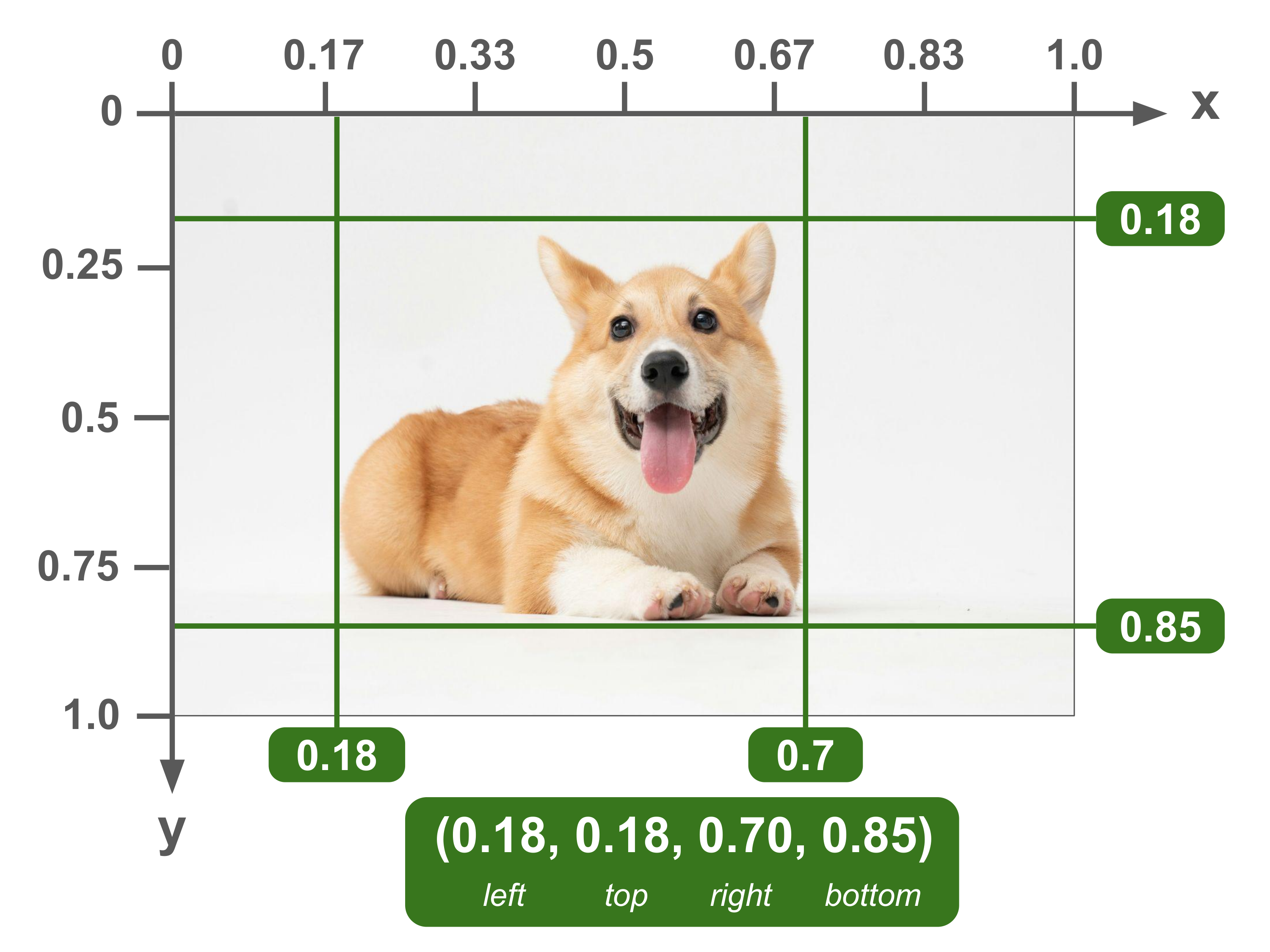
(left, top, right, bottom)
Also known as (x_min, y_min, x_max, y_max)
In this format, the first two numbers indicate the xy coordinates of the top-left point of the bounding box. The last two numbers indicate the xy coordinates of the bottom-right point of the bounding box.
From these two points, the coordinates of the other two points and thus the whole box can be inferred. For example, the xy coordinates of the top-right point are simply the first (top) and last (right) numbers combined.
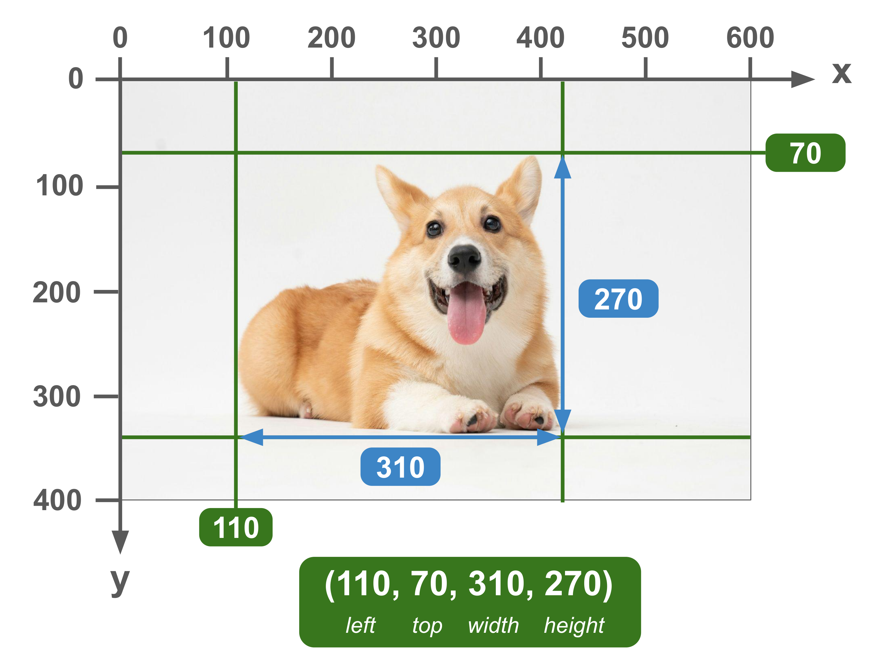
(left, top, width, height)
Also known as x_min, y_min, width, height
In this format, the first two numbers indicate the xy coordinates of the top-left point of the bounding box. The last two numbers indicate the width and height of the bounding box.
From this information, the coordinates of the other three points can be inferred. For example, the x coordinates of the top-right point are the first (top) number — sub in the photo of the box with points

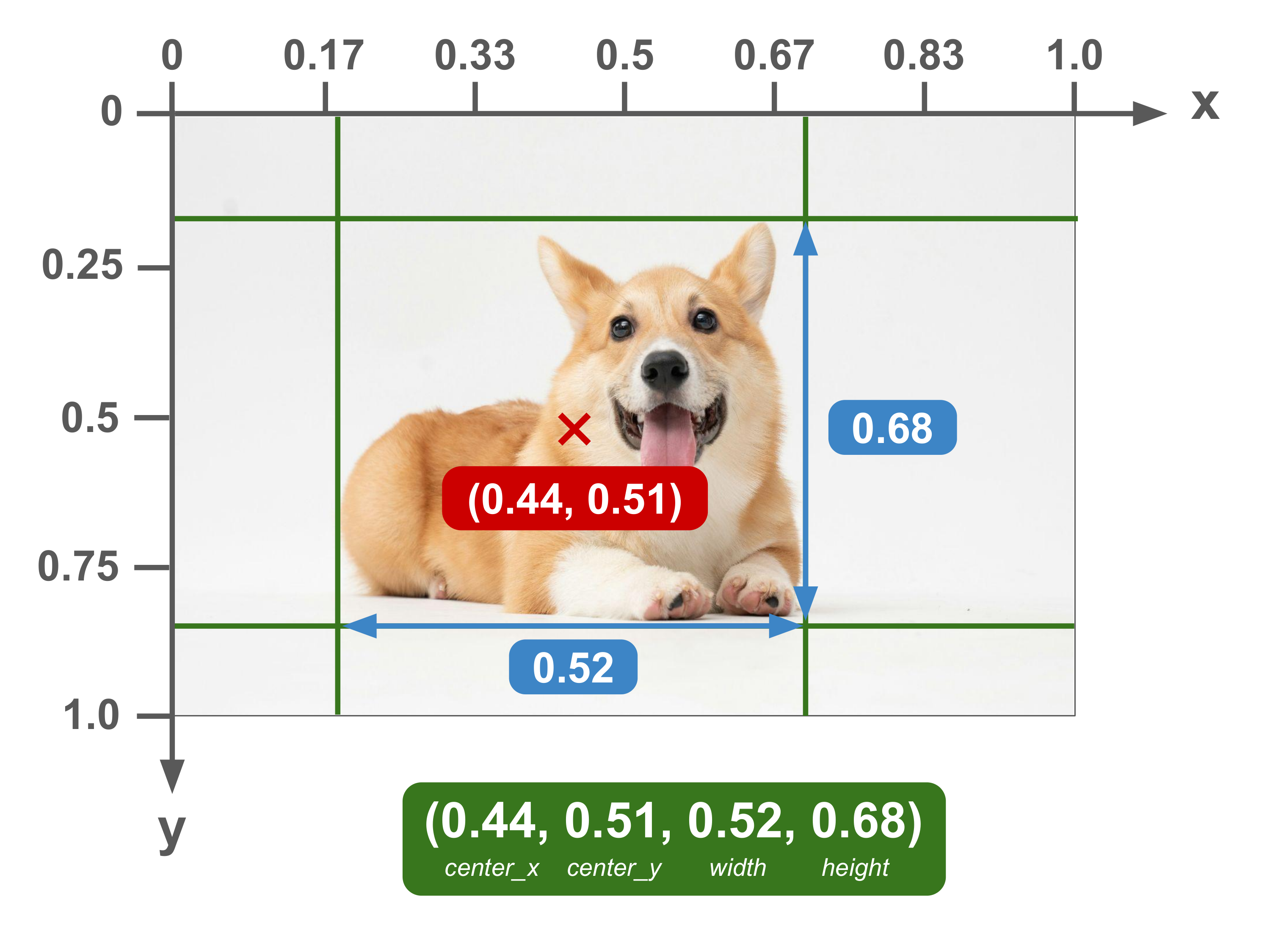
(center_x, center_y, width, height)
In this format, the coordinates of the center of the bounding box are indicated by the first two numbers, followed by the width and height of the bounding box.
While this approach doesn’t give you any of the four corners of the bounding box, you can still easily calculate them by adjusting the center point.

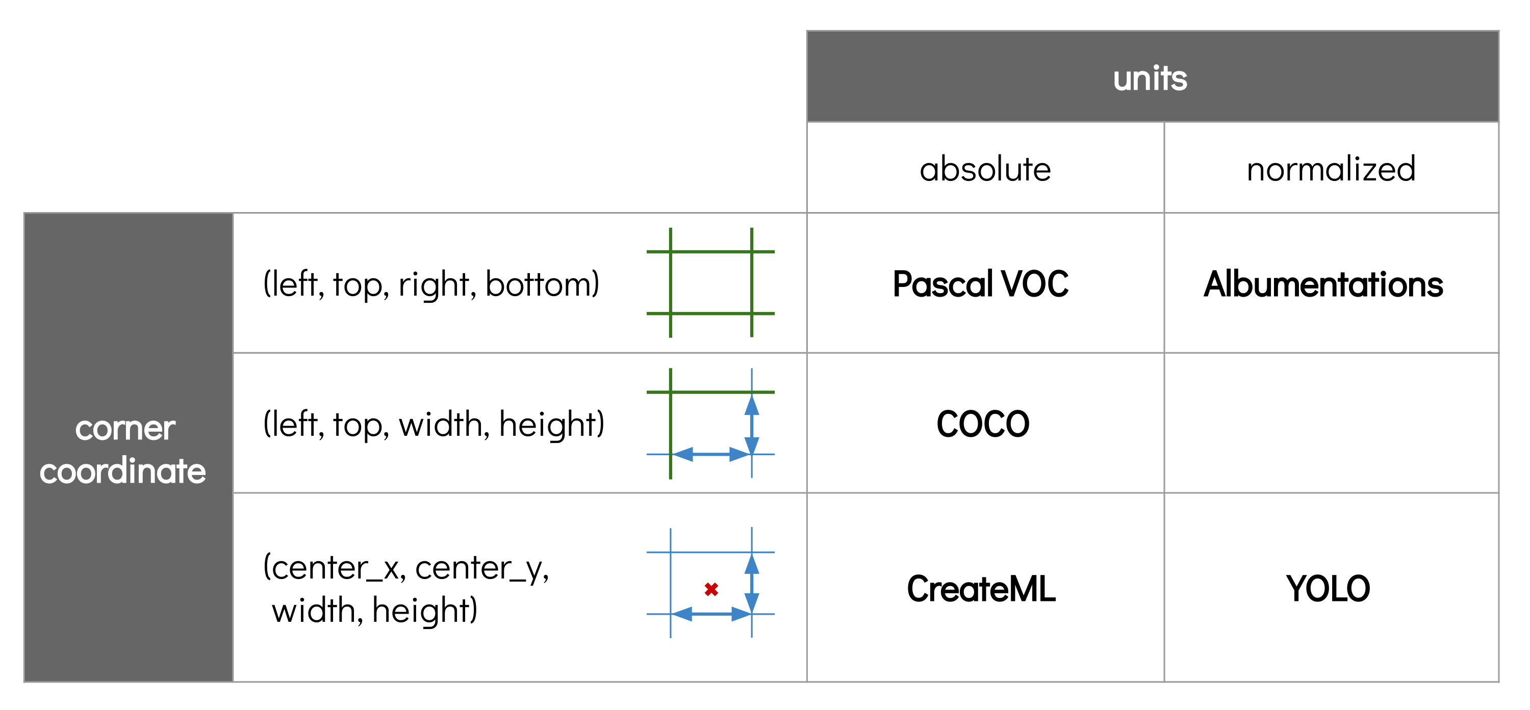
Common Formats
All of the common formats that you will out there are basically a combination of one method of corner specification and one unit type. Here is a summary table of all of the different formats:
Pascal VOC
Units: Absolute | Corner Specification: (left, top, right, bottom)
Also known as: xyxy
One of the most common formats, this format is named after the Pascal VOC dataset which used it.

Albumentations
Units: Normalized | Corner Specification: (left, top, right, bottom)
Also known as: xyxyn
This format is used by the Albumentations image augmentation library.
COCO
Units: Absolute | Corner Specification: (left, top, width, height)
Also known as: xywh
Named after the popular COCO dataset, this is perhaps the most common bounding box format used in datasets currently.
In addition to the bounding box format, the COCO dataset also introduced a standardized format for object detection and segmentation labels. Because of the importance of the COCO dataset in computer vision, all of these are now pretty much the standard for datasets today.
YOLO
Units: Normalized | Corner Specification: (center_x, center_y, width, height)
Also known as: cxcywhn
This format was popularized by the YOLO family of models, including YOLOv5, YOLOv8, and YOLO-World.. The reason to use the center coordinate as an anchor instead of the top-left was because the YOLO models directly predicted the center of the boxes, so this data format made it easier.
CreateML
Units: Absolute | Corner Specification: (center_x, center_y, width, height)
Also known as: cxcywh
The default in Apple’s CreateML MLObjectDetector. It is probably the least used of the 5 formats listed here.

Summary
That’s basically it! Hopefully this article helped to demystify the differences between the various bounding box formats that you encounter in your computer vision journey.
If you want get hands on with bounding boxes in code, I highly recommend A Guide to Bounding Box Formats and How to Draw Them by Daniel Bourke over at learnml.io. In it, they have a code-along that shows you how to manipulate bounding boxes in Python and visualize them. Otherwise, happy coding!